

Temperature Controlled Fan
Temperature Controlled Fan
Aim:
The main aim of the project is to measure temperature and if the temperature increases then the Fan will ON automatically on TeBoT.
Components Required:
| Sr. No | Component | Quantity |
|---|---|---|
| 1 | TeBoT and cable | 1 |
| 2 | TeBoT Connector | 1 |
| 3 | DHT11 | 1 |
| 4 | LCD_I2C | 1 |
| 5 | DC Motor | 1 |
| 6 | 1 Channel Relay Module | 1 |
| 7 | Jumper Cable(M-F) | 5 |
| 8 | Jumper Cable(F-F) | 5 |
| 9 | Jumper Cable(M-M) | 3 |
| 10 | Battery | 1 |
Connection and Code Upload:
Step 1: Connect the TeBoT with your device and turn on it.
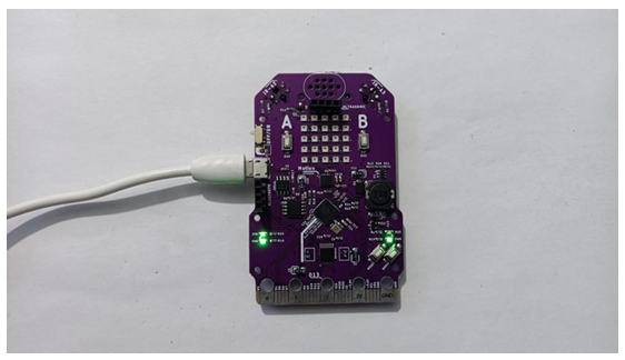
Step 2: Select the board and port, then upload the code.
Warning: If you face any issue while uploading the code, first “OFF” the TeBoT. Next, turn “ON” the TeBoT. Press the “BOOT” button for a short time then press the “RESET” button once. Then release the “BOOT” button. You will get a drive. Then upload the code.
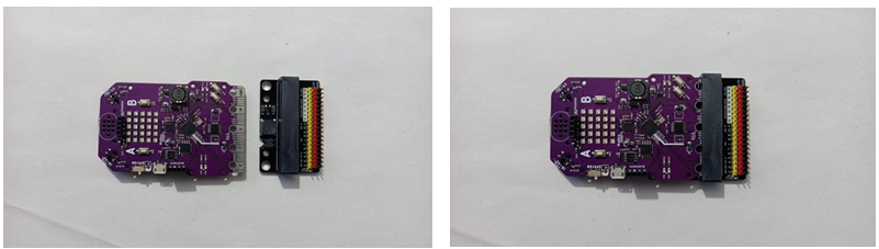
Step 3: Take the connector and attach on TeBoT.
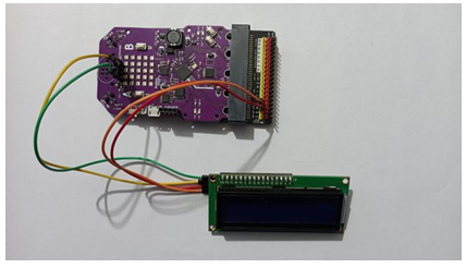
Step 4: Connect the LCD with TeBoT and connector.
| LCD_I2C | ↔ | TeBoT |
|---|---|---|
| GND | ↔ | GND (1st pin from left to right in ultrasonic port) |
| VCC | ↔ | VCC (1st pin from right to left in ultrasonic port) |
| SDA | ↔ | Pin no 4 (Connector) |
| SCL | ↔ | Pin no 5 (Connector) |
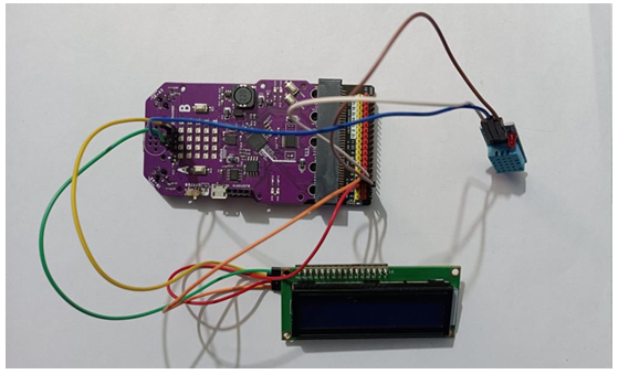
Step 5: Connect DHT11 with TeBoT.
- VCC of DHT11 with VCC (Connector) of TeBoT.
- GND of DHT11 with GND (Connector) of TeBoT.
- OUT of DHT11 with Pin no 14 (2nd pin from left to right in ultrasonic port) of TeBoT.
Step 6: Now Connect the relay module with TeBoT.
- VCC of Relay with VCC (4th pin from up to down in bluetooth port) of TeBoT.
- GND of Relay with GND (3rd pin from up to down in bluetooth port) of TeBoT.
- IN of Relay with Pin No 3 (Signal pin) of Connector.
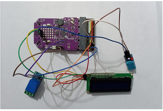
Step 7: Now take the motor and connect with relay module and battery.
- Connect the +VE of motor with NC of Relay.
- Connect the –VE of motor with –VE of Battery.
- Connect COM of Relay with +VE of Battery.
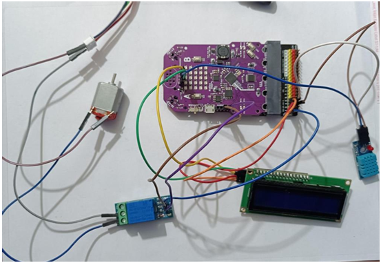
Now, turn on the TeBoT. You will see the temperature on LCD screen. If the temperature crosses 40 then the fan will be ON with the help of relay.
Conclusion: From this project we got the idea about all components, connection of those components and made the Temperature Controlled Fan.